|
UHA 9105
|
|
UHA 9125 C
 |
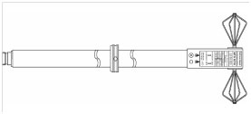
Tuneable UHF – Half – Wave Dipole with EMI – Balun, 0.75 – 2 GHz with 4 sets of elements, LE = 180, 140, 100, 80 mm.
[Radiation Pattern] [VSWR]
|
|
|
UHA 9125 D
|
|
VHAP
 |
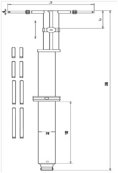
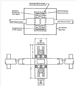
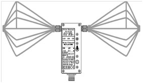
VHF Precision Dipole 30-300 MHz, 2 sets of telescopic elements (mostly required in pairs) CISPR 16-1-5 [Manual]
|
|
|
UHAP
| |
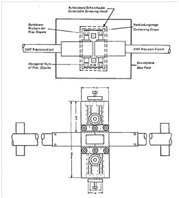
UHF Precision Dipole 300-1000 MHz (VHAP & UHAP mostly required in pairs) CISPR 16-1-5 [Manual]
|
|
|
CCA
| |
Carrying and storing case for 2 x VHAP or 2 x UHAP, cases for other antennas also available
|
|
|
VHAPA
 |
Calibration adaptor for VHAP Precision Dipoles
|
|
|
UHAPA
 |
Calibration adaptor for UHAP Precision Dipoles
Handy-, FM- and TV bands antennas
|
|
|
FT 01 S
 |
Additional elements for enhanced FM broadcast directivity
|
|
|
FT 01 UKW
| |
FM broadcast and TV bands antenna, detachable, 47 – 860 (1000) MHz, high directivity
|
|
|
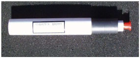
NMHA
| |
Nissan and Renault antenna set to test immunity against handy transmitters acc. to Nissan specification 28401NDS02 [4] August 2008 and RENAULT 36-00-808/L 2010 (combined set) consisting of normal mode helical antennas, dipoles counterpoise and transport case (see extra list)
|
|
|
WAND0918
 |
Wireless Immunity “Wand” Antenna acc. to Dell Specification „SYSTEM IMMUNITY TO WIRELESS GSM TEST REQUIREMENT” 800 MHz -2 GHz.
|
|
|
BBHA 9120 A
|
|
BBHA 9120 B
|
|
BBHA 9120 C
|
|
BBHA 9120 D
|
|
BBHA 9120 E
|
|
BBHA 9120 F
|
|
BBHA 9120 F Opt 7/16
| |
Option: with 7/16-connector 3 kW
|
|
|
BBHA 9120 F Opt. 1 m
 |
Very short telescopic tube to be inserted into the steel foot of AM 9144 to set BBHA 9120 F to a height of 1 m referring to the antenna center in both polarisations
|
|
|
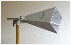
BBHA 9120 G
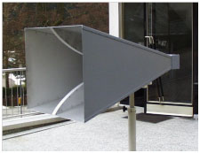 |
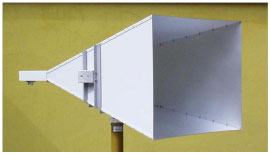
Broad-Band Horn Antenna 0.4 – 2.8 GHz, 7/16-connector
|
|
|
BBHA 9120 LF
|
|
BBHA 9120 L3F
|
|
BBHA 9170
 |
Broad-Band Horn Antenna 15 – 26.5 (40) GHz, SMA-compatible connector
[VSWR] [Picture]
|
|
|
HA 9250-24
 |
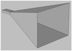
Pyramidal standard gain horn Antenna, 2 – 4 GHz, 7/16-connector, 20 dBi, optimized for far field gain
|
|
|
HA 9250-48
 |
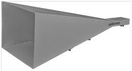
Pyramidal Horn Antenna, 4 – 8 GHz, 7/16-connector, 20 dBi, optimized for far field gain.
|
|
|
HA 9251-24
 |
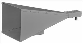
Pyramidal standard gain horn Antenna, 2 – 4 GHz, 7/16-connector, 18 dBi, optimized for the gain in 1 m distance.
|
|
|
HA 9251-48
 |
Pyramidal standard gain horn Antenna, 4 – 8 GHz, 7/16-connector, 19 dBi, optimized for the gain in 1 m distance.
|
|
|
BBHX 9120 E
|
|
BBHX 9120 LF
 |
Dual polarized Broad-Band Horn Antenna (0.8) 1 – 8 (10.5) GHz, N-connectors.
|
|
|
SGA
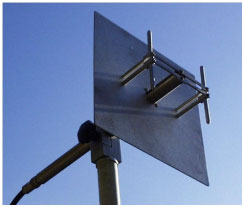 |
Standard Gain Antennas, typ. 9.8 dBi gain, 60° pattern, accurately calibrated (2 half-wave dipoles in front of a lambda x lambda reflector, design frequencies approx. 400-2800 MHz SGA 900 SGA 1800
|
|
|
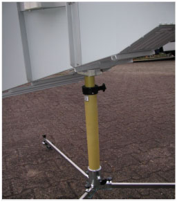
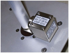
VAMP 9243
| |
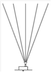
Vertikal active rod antenna, 9 kHz - 30 MHz, BNC, reduced noise floor, with mounting nut for AM 9144 and rechargeable battery.
|
|
|
VAMP 9243 Opt. GP
| |
Option: Aluminium-Groundplane, 0.6 x 0.6 m
|
|
|
VAMP 9243 Opt. ACS 410
|
|
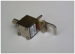
VAMP 9243 Opt. VT
 |
Option 20 dB plug in divider to measure high field strength [Picture]
|
|
|
VAMP 9243 Opt. CA 9243
 |
Calibration Adapter for VAMP 9243
|
|
|
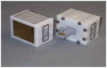
EFS 9218
 |
Active Electric Field Probe with Biconical Elements, 9 kHz - 300 MHz, 12 µV/m - 65 V/m, const. antenna factor typ. 46 dB/m high symmetry, built in rechargeable battery. The swtchable preamplifier improves the antenna factor to 20 dB/m.
|
|
|
EFS 9218 Opt. ACS 410
| |
Option: Automatic charger ACS 410 for EFS 9218
|
|
|
EFS 9219
 |
Active antenna holder, high sensitivity (1 µV/m … 3 V/m), 9 kHz-30 MHz, BBUK 9139 biconical elements required.
|
|
|
EFS 9219 Opt. Rohr
| |
Option: Isolating tube with braid chokes for EFS 9219
|
|
|
EFS 9219 Opt. ACS 410
| |
Option: Automatic charger Ansmann ACS 410 for EFS 9219
|
|
|
VPMP 9242
 |
Vertical passive rod antenna, 10 - 40 MHz, possible rods: FBAB 9177, FBAL 9178, BBA 9106, BBAL 9136 ( rod must be ordered extra)
|
|
|
VPMP 9242 Opt. GP
| |
Option: Aluminium groundplane 0.6 x 0.6 m
|
|
|
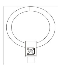
HFRA 5148
| |
Circular Transmitting Loop Antenna diam. 180 mm, 1 turn
|
|
|
HFRA 5149
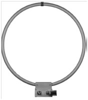 |
Circular transmitting loop antenna 9 kHz – 30 MHz, diam. 500 mm including 50 Ohm 20 Watt termination, N-connectors.
|
|
|
HFRA 5152
 |
Circular Transmitting Loop Antenna diam. 250 mm, DC-3 MHz
|
|
|
HFRA 5153
| |
Circular Transmitting Loop Antenna diam. 180 mm, 0-20 (30) MHz, 5 W
|
|
|
HFRA 5154
 |
Circular Transmitting Loop Antenna diam. 100 mm, 0.1 – 30 MHz, Transformer 50 Ohm, 0.5 W
|
|
|
HFRA 5155
| |
Circular Transmitting VHF – UHF loop antenna, diam. 50 mm,
|
|
|
HFRA 5156
| |
Circular Transmitting Loop Antenna diam. 50 mm, 0-5 MHz, 2 W, 10 turns
|
|